目录
Bulid a circuit from a simulation waveform
写在前面
HDLBits 刷题来到了最为重要的一部分---有限状态机,都说 Verilog 设计的精髓就是状态机的设计,可见状态机设计的重要性,通过三十多道的状态机的练习,可以更加熟悉状态机设计的要点,通常都设计为三段式,这样设计的状态机层次清晰且易于设计,时序上更为易懂。以下的解题方法不一定为最佳解决方案,有更好的方法欢迎提出,共同学习,共同进步!
Finding bugs in code
Bugs mux2
module top_module (
    input          sel,
    input  [7:0]   a,
    input  [7:0]   b,
    output [7:0]   out
);

    assign out = sel?a:b ;

endmodule
Bugs nand3
module top_module (
	input      a,
	input      b,
	input      c,
	output     out
);

reg    out_reg;

assign out = ~out_reg;

andgate inst1 (out_reg, a, b, c, 'd1, 'd1);

endmodule
Bugs mux4
module top_module (
    input  [1:0]    sel,
    input  [7:0]    a,
    input  [7:0]    b,
    input  [7:0]    c,
    input  [7:0]    d,
    output [7:0]    out
);

    wire [7:0]  mux0, mux1;
    mux2 mux0_inst ( sel[0],    a,    b, mux0 );
    mux2 mux1_inst ( sel[0],    c,    d, mux1 );
    mux2 mux2_inst ( sel[1], mux0, mux1,  out );

endmodule
Bugs addsubz
module top_module (
    input              do_sub,
    input      [7:0]   a,
    input      [7:0]   b,
    output reg [7:0]   out,
    output reg         result_is_zero
);

    always @(*) begin
        case (do_sub)
          0: out = a+b;
          1: out = a-b;
        endcase

        if (out=='d0)
            result_is_zero = 'd1;
        else
        	result_is_zero = 'd0;
    end

endmodule
Bugs case
module top_module (
    input      [7:0]   code,
    output reg [3:0]   out,
    output reg         valid
);

    always @(*) begin
     	valid = 'd1;
        case (code)
            8'h45: out = 0;
            8'h16: out = 1;
            8'h1e: out = 2;
            8'h26: out = 3;
            8'h25: out = 4;
            8'h2e: out = 5;
            8'h36: out = 6;
            8'h3d: out = 7;
            8'h3e: out = 8;
            8'h46: out = 9;
            default: begin
    	           valid = 0;
				   out = 0;
            end
        endcase
    end
endmodule
Bulid a circuit from a simulation waveform
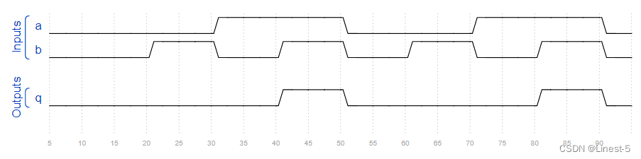
circuit1
这是一个组合电路。读取仿真波形以确定电路的作用,然后实现它。
module top_module (
input a,
input b,
output q
);
assign q = a&b;
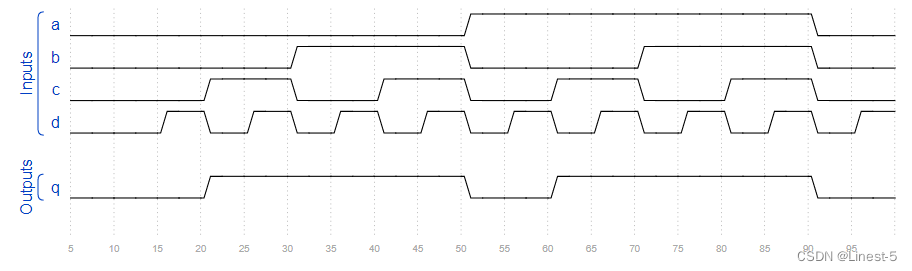
endmodulecircuit2
这是一个组合电路。读取仿真波形以确定电路的作用,然后实现它。

module top_module (
    input    a,
    input    b,
    input    c,
    input    d,
    output   q
);

    assign q = ~(a^b^c^d); // Fix me

endmodule
circuit3
这是一个组合电路。读取仿真波形以确定电路的作用,然后实现它。

module top_module (
    input     a,
    input     b,
    input     c,
    input     d,
    output    q
);

    assign q = b&d | a&d | b&c | a&c ;

endmodule
circuit4
这是一个组合电路。读取仿真波形以确定电路的作用,然后实现它。
module top_module (
input a,
input b,
input c,
input d,
output q
);
assign q = b|c;
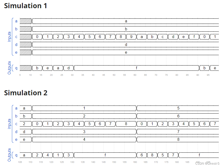
endmodulecircuit5
这是一个组合电路。读取仿真波形以确定电路的作用,然后实现它。
module top_module (
input [3:0] a,
input [3:0] b,
input [3:0] c,
input [3:0] d,
input [3:0] e,
output [3:0] q
);
always @(*) begin
case(c)
0: begin
q = b;
end
1: begin
q = e;
end
2: begin
q = a;
end
3: begin
q = d;
end
default:begin
q = 'd15;
end
endcase
end
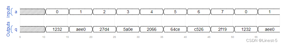
endmodulecircuit6
这是一个组合电路。读取仿真波形以确定电路的作用,然后实现它。
module top_module (
    input  [2:0]    a,
    output [15:0]   q
);

always @(*) begin
	case(a)
		0:  q = 16'h1232;
		1:  q = 16'haee0;
		2:  q = 16'h27d4;
		3:  q = 16'h5a0e;
		4:  q = 16'h2066;
		5:  q = 16'h64ce;
		6:  q = 16'hc526;
		7:  q = 16'h2f19;
	endcase
end

endmodule
circuit7
这是一个时序电路。读取仿真波形以确定电路的作用,然后实现它。
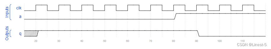
module top_module (
    input   clk,
    input   a,
    output  q
);

always @(posedge clk) begin
	q <= ~a;
end

endmodule
circuit8
这是一个时序电路。读取仿真波形以确定电路的作用,然后实现它。
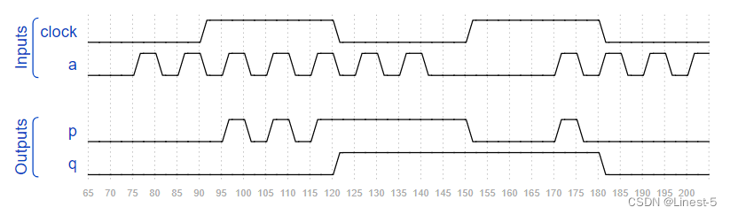
module top_module (
    input     clock,
    input     a,
    output    p,
    output    q
);

always @(*) begin
	if (clock) begin
		p = a;
	end
	else begin
		p = p;
	end
end

always @(negedge clock) begin
	q <= a;
end

endmodule
circuit9
这是一个时序电路。读取仿真波形以确定电路的作用,然后实现它。
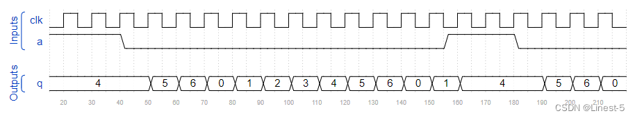
module top_module (
    input         clk,
    input         a,
    output [3:0]  q
);

always @(posedge clk) begin
	if (a) begin
		q <= 'd4;
	end
	else if (q=='d6) begin
		q <= 'd0;
	end
	else begin
		q <= q + 'd1;
	end
end

endmodule
circuit10
这是一个时序电路。读取仿真波形以确定电路的作用,然后实现它。
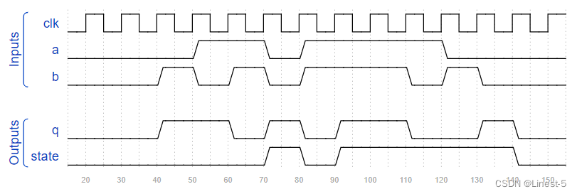
module top_module (
    input      clk,
    input      a,
    input      b,
    output     q,
    output     state
);

assign q = a^b^state;

always @(posedge clk) begin
	if (a&b) begin
		state <= 'd1;
	end
	else if (~a&~b) begin
		state <= 'd0;
	end
	else begin
		state <= state;
	end
end

endmodule